8/22/15

LINEARITY PROPERTY, SUPERPOSITION AND SOURCE TRANSFORMATION


*LINEAR PROPERTY
-linear network consist of linear elements, linear dependent sources and linear independent sources.

It is state that the output of linear circuit is directly proportional to its input.

LINEAR SYSTEM HAVE TWO IMPORTANT AND USEFUL PROPERTIES:
-Superposition
-Homogeneity


*SUPERPOSITION
- Superposition states that the voltage across an element in linear circuit is the algebraic sum of the  voltages across that element due to each independent source acting alone.


WAYS OR TECHNIQUES IN SOLVING THIS CIRCUIT:


-Turn off, killed, inactive source:
-independent voltage source: 0 V (short circuit)
-independent current source: 0 A (open circuit)
-Dependent sources are left intact.


After you apply those techniques above, proceed to the steps in solving superposition.

STEPS TO APPLY THE PRINCIPLE:
1.Turn off all independent sources except one source. Find the output voltage or current due to that active source using mesh analysis or nodal analysis.
2.Repeat step 1 with other independent sources.
3.Find the total contribution by adding directly all of the contributions of independent sources.

In killing the independent sources, first you need to turn off all the sources(current and voltage) short the voltage source and open the current source and make their voltages and currents equal to zero.


SAMPLE OF A SUPERPOSITION CIRCUIT:
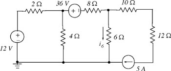


SAMPLE PROBLEM:
Find the voltage Vx using superposition


*SOURCE TRANSFORMATION
-Source transformation talks about simplifying a circuit especially with complicated or mixed sources. By transforming the voltage sources into current sources and current sources into voltage sources using ohms law V=IR.


Sample Problem :
(this sample problem is unfinish but we only post this sample in order to explain properly the transformation)


8/15/15

MESH ANALYSIS


Mesh Analysis


Mesh analysis is the method that is used to solve planar circuits for the currents at any place in the circuit. We first note that the mesh current method is only applicable for “planar” circuits.


Planar circuits have no crossing wires when drawn on a plane. Often, by redrawing a circuit which appears to be non-planar, you can determine that it is in fact, planar.


Mesh analysis works by arbitrarily assigning mesh currents in the essential meshes (also referred to as independent meshes). An essential mesh is a loop in the circuit that does not contain any other loop.


A mesh current is a current that loops around the essential mesh and the equations are set solved in terms of them. A mesh current may not correspond to any physically flowing

current, but the physical currents are easily found from them.


Mesh Analysis with Current Sources


In mesh analysis there are two cases we need to consider:


Case 1- A current sources exist only in one mesh

- Set the mesh currentt = current source


Case 2- A current source between two meshes are called

supermesh


A supermesh occurs when a current source is contained between two essential meshes. The circuit is first treated as if the current source is not there. This leads to one equation that incorporates two mesh currents. Once this equation is formed, an equation is needed that relates the two mesh currents with the current source. This will be an equation where the current source is equal to one of the mesh currents minus the other.


Mesh Analysis without Current Sources


1. Assign mesh currents to the meshes. Assume mesh current flows clockwise.


2.Apply KVL


7/24/15

Nodal Analysis With Voltage Source


Nodal Analysis With Voltage Source


There are three things which we should consider before doing the nodal analysis;

First: We should identify and point out how many nodes are present in the circuit given.

Second: If a supernode is present, consider in mind that a supernode has no voltage identified as its own.

Third: Put a reference node. 


Remember that voltage source affects the nodal analysis and we should analyze the possibilities and the pros and cons. There are cases to be followed especially in doing the analysis of the nodes.

CASE 1.

        If the voltage source is connected between the reference node and non-reference node, the non-reference node is equal to the voltage source.


CASE 2.

        If the voltage source is connected into two non-reference node. The non-reference node is called a SUPERNODE.

* KCL and KVL are to be applied to determine the voltages on that par

There are three nodes present in this circuit. Nodes V1, V2, & V3.
Defined from our last blog, a supernode means closed surface connected with a voltage source and two nodes.
Therefore, the node formed V2 & V3 is called a SUPERNODE.

7/18/15

NODAL ANALYSIS WITH CURRENT SOURCES

GOOD DAY! :)


First of all, we want to introduce to you this new topic in our blog.


WHAT IS A NODAL ANALYSIS?

A nodal analysis is a method of determining or identifying the voltage or the potential difference between the nodes in an electric circuit in terms of the branch currents. In this case, choosing a node voltage is easier than choosing other elements as current variables.


WHAT IS A NODE?

A node is a point where elements or branches are connected.


WHAT ARE THE STEPS IN DETERMINING NODE VOLTAGES?

STEP 1. Choose a node as the reference node. A reference node is a node with 0 potential.

STEP 2. Assign voltages V1, V2... Vn-1 to the remaining n-1 nodes. The voltages are referenced with respect to the reference node.

STEP 3. Apply KCL to each of the n-1 non-reference nodes. Use Ohm's law to express the branch currents in terms of node voltages.

STEP 4. Solve to determine the unknown node voltages. Use substitution method or Cramers rule.

7/11/15

Wye - Delta Transformation

G'day, mates :)

This is the continuation of our previous blog last week. So, if you start wondering what are these triangles and y's doing in the circuit here's why:

The transformation is used to establish equivalence for networks with three terminals. Where three elements terminate at a common node and none are sources, the node is eliminated by transforming the impedance. For equivalence, the impedance between any pair of terminals must be the same for both networks. 


Now, I will start answering the questions from your curious, little minds. HOW TO TRANSFORM A CIRCUIT FROM Wye to Delta, and vice-versa Delta to Wye? 

Detailed equations and formulas are to be precisely used  to get the value on y's and on deltas. So, to all the clumsy and happy-go-lucky mates out there, this is a big perimeter-securing on your part.


DELTA to Y:


Formula in getting the Y-values are the following:

R1 = RbRc / (Ra+Rb+Rc)

R2 = RaRc / (Ra+Rb+Rc)

R3 = RaRb / (Ra+Rb+Rc)

There's a technique in doing this without using any formula, if you're asked to get the y-value the resistors which are on its adjacent sides are to be multiplied then divide it to the sum of all the resistors in the circuit. TAKE NOTE: "ADJACENT".

Y to DELTA:

Ra = (R1R2+R2R3+R3R1) / R1

Rb = (R1R2+R2R3+R3R1) / R3

Rc = (R1R2+R2R3+R3R1) / R2

Some say that Y to DELTA is very complex because some circuits in WYE-DELTA TRANSFORMATION are placed in neither parallel nor series connections.


If you have doubts about our blog please try to solve this diagram and mail us at dominiclargo@gmail.com. THANK YOU. GOODBYE.